Embedded ARM Part 0: STM32 programming with libopencm3
Tue, Sep 11, 2018 Companion code for this post available on GithubFor many years now, I have found myself building (admittedly small) electronics projects, and for almost all of that time I have found myself reaching for the same microcontroller: the humble Atmega 328p that powers so many Arduinos (and Arduino clones!). This choice was driven by the fact that being an Arduino-compatible MCU meant I could take advantage of the huge library of code built for the Arduino platform. However, the choice is somewhat limiting - with only 16KiB of flash and 2KiB of sram, some applications were simply infeasible within that range. In addition, the relatively slow 16MHz top speed can make high-data-rate applications, like display driving, somewhat of a challenge.
Luckily, there are a number of increasingly cheap ARM based MCUs on the market.
In particular, ST has an excellent lineup, including a ‘value line’ of F0
series MCUs that offer a lot of features (128K flash, 16K sram, multiple SPI /
I2C / Timer / DMA peripherals) for relatively cheap. However, a lot of the
proprietary development environments (such as the graphical STMCube software)
seem to me overly complex, and make it difficult to use preferred editors /
development toolchains. Luckily, there is an open source low-level hardware
abstraction library with coverage for the STM32 series of MCUs, called
libopencm3.
Using this, it is easy to write portable C(++) code that can easily be deployed
using only GNU tools. In this tutorial, I will attempt to cover the basics of
starting a new project with libopencm3, compiling, uploading code, and the
use of the SysTick peripheral.
The full source code for this tutorial, along with the EAGLE and Gerber files for the breakout board I used, are available in this Github repo.
Equipment
Since my goal was to be able to use these MCUs in my own designs, I am not using an off-the-shelf development board from ST, but an extremely basic breakout of my own design with nothing but an STM32F070CBT6, a Single-Wire Debug (SWD) header and all IO pins on the MCU broken out to .1” headers. These instructions should however work for any board with an STM32FX part, so long as it has a SWD header.
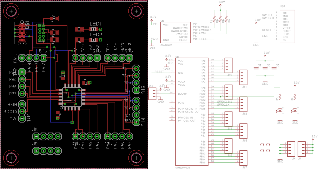
Breakout board and schematic. Source materials available in Github.
The only other important piece of kit is a Black Magic probe. The BMP is a fantastic little device - it provides a GDB server that makes it simple to upload code to the MCU, debug it, and also has a UART interface so that you can wire it up to get a debug console. It can be found online for ~$60USD at time of writing.
Foundation
The very first thing we are going to do is acquire a copy of libopencm3 to
compile against. In order to make sure that we don’t end up with any dependency
drift, I am going to add it as a
submodule
to our new git project. So let’s
start by creating a new project, and cloning it in:
$ mkdir hello_opencm3
$ cd hello_opencm3/
$ git init .
$ git submodule add https://github.com/libopencm3/libopencm3.git
$ git commit -m "Import opencm3"
Now, we need to build opencm3 so that we can link against it later.
If you do not have GCC for ARM installed, you may need to install it now.
For Debian and kin, the following will install everything you might need for
this tutorial:
$ sudo apt install {gcc,gdb,libnewlib,libstdc++,binutils}-arm-none-eabi
Now, we can drop into the libopencm3 dir and build.
Note that if you have custom CFLAGS or CXXFLAGS set for your host machine,
you may need to unset them if they are unsupported by gcc-arm.
$ pushd libopencm3
$ unset CFLAGS && unset CXXFLAGS # You may not need to do this
$ make
$ popd
Now that we have our library ready, it’s time to start writing some code. To
begin, let’s just start by blinking the LED I have attached to pin PA11. If you
are using a different test board, you may need to sub out GPIOA and GPIO11
to match the port and pin you are using instead.
#include <libopencm3/stm32/rcc.h>
#include <libopencm3/stm32/gpio.h>

int main() {
    // First, let's ensure that our clock is running off the high-speed
    // internal oscillator (HSI) at 48MHz
    rcc_clock_setup_in_hsi_out_48mhz();

    // Since our LED is on GPIO bank A, we need to enable
    // the peripheral clock to this GPIO bank in order to use it.
    rcc_periph_clock_enable(RCC_GPIOA);

    // Our test LED is connected to Port A pin 11, so let's set it as output
    gpio_mode_setup(GPIOA, GPIO_MODE_OUTPUT, GPIO_PUPD_NONE, GPIO11);

    // Now, let's forever toggle this LED back and forth
    while (true) {
        gpio_toggle(GPIOA, GPIO11);
    }

    return 0;
}
This is very basic, but it’s something we can compile to ensure we’re able to load code at all. Later on we will refine this example. But first, we need to build a linker script
Linker scripts
As part of compiling our code, we need to specify where in our MCU memory
to place both the code as well as our memory. In order to do this, we first
need to look up the address space map for our CPU. From the STM32F070
datasheet, we see that the ‘Flash Memory’ block resides at 0x08000000 and is
128KiB in size, while the main ram (SRAM) lives at 0x20000000 and is 16KiB in
size. Armed with this information, we can create our linker script with these
two sections:
MEMORY {
    rom (rx) : ORIGIN = 0x08000000, LENGTH = 128K
    ram (rwx) : ORIGIN = 0x20000000, LENGTH = 16K
}

INCLUDE cortex-m-generic.ld
OpenCM3 proves the cortex-m-generic.ld script, which takes our rom/ram
definitions to locate the stack, as well as specify the locations of the
.text, .data, .bss and other sections. It’s fairly short, so it’s worth
taking a look if you’re curious about the details of how sections are laid out
in memory.
Building
Now that we have our device-specific linker data, we can get to compiling. I’ve posted this example project on Github including the full Makefile that defines the build rules necessary to compile our project. The core variables in that makefile are
OBJS: The list of.ofiles to compile. Since we only have the one source file,main.cpp, we have only one object file,main.o.OPENCM3_DIR: The location of opencm3 relative to our project. In this case, it is in the same directory.LDSCRIPT: The linker script to use. Set this to the one we made earlier.LIBNAMEandDEPS: The precise chip variant that we are compiling for. This controls which includes are matched from opencm3, and which support library is linked against.
To try and keep this short, I won’t go over the entire makefile here. However, here are the two commands, in full, used to compile and link our simple binary. I have gone through and annotated each flag, which will hopefully explain why they are present.
$ arm-none-eabi-g++ \
    -Os \ # Optimize for code size
    -ggdb3 \ # Include additional debug info
    -mthumb \ # Use thumb mode (smaller instructions)
    -mcpu=cortex-m0 \ # Target CPU is a Cortex M0 series
    -msoft-float \ # Software floating-point calculations
    -Wall \ # Enable most compiler warnings
    -Wextra \ # Enable extra compiler warnings
    -Wundef \ # Warn about non-macros in #if statements
    -Wshadow \ # Enable warnings when variables are shadowed
    -Wredundant-decls \ # Warn if anything is declared more than once
    -Weffc++ \ # Warn about structures that violate effective C++ guidelines
    -fno-common \ # Do not pool globals, generates error if global redefined
    -ffunction-sections \ # Generate separate ELF section for each function
    -fdata-sections \ # Enable elf section per variable
    -std=c++11 \ # Use C++11 standard
    -MD \ # Write .d files with dependency data
    -DSTM32F0 \ # Define the series of MCU we are using. This controls the
              \ # include pathways inside libopencm3.
    -I./libopencm3/include \ # Include the opencm3 header files
    -o main.o \ # Output filename
    -c main.cpp # Input file to compile

$ arm-none-eabi-gcc \
    --static \ # Don't try and use shared libraries
    -nostartfiles \ # No standard lib startup files
    -Tstm32f0.ld \ # Use the linker script we defined earlier
    -mthumb \ # Thumb instruction set for smaller code
    -mcpu=cortex-m0 \ # Cortex M0 series MCU
    -msoft-float \ # Software floating point
    -ggdb3 \ # Include detailed debug info
    -Wl,-Map=main.map \ # Generate a memory map in 'main.map'
    -Wl,--cref \ # Output a cross-reference table to the mem map
    -Wl,--gc-sections \ # Perform dead-code elimination
    -L./libopencm3/lib \ # Link against opencm3 libraries
    main.o \ # Our input object(s)
    -lopencm3_stm32f0 \ # The opencm3 library for our chip
    \ # Begin and end group here allow resolving of circular dependencies
    \ # while linking. This links against some common libs:
    \ # -lc: the standard C library
    \ # -lgcc: GCC-provided subroutines
    \ # -lnosys: Stub library with empty definitions for POSIX functions
    -Wl,--start-group -lc -lgcc -lnosys -Wl,--end-group
    -o main.elf # Our output binary
Once I’ve built my code, I also like to print a quick summary of the size so
that I can track how much of my flash and memory is currently consumed. For
this, we can use the arm-none-eabi version of size:
$ arm-none-eabi-size main.elf
  text    data     bss     dec     hex filename
  7832    2120      60   10020    2724 main.elf
So far we’re already using 7k of flash data, and 2k of initialized memory. Only 60 bytes of globally allocated variables however! Now that we have our binary, it’s time to flash it to our microcontroller.
Flashing
In order to load this code, we’re going to turn to GDB. Since our Black Magic
Probe runs a GDB server, we use it as a remote target. First, ensure that the
10-pin SWD cable is connected to your board in the correct orientation. You
must also be sure to supply power to your board - the BMP will not supply power
to the board itself. Once you’ve done this, we can open up arm-none-eabi-gdb:
$ arm-none-eabi-gdb main.elf
# First, we need to tell GDB to use our BMP as a remote target.
# /dev/ttyACM0 is where it shows up on my machine, but YMMV
(gdb) target extended-remote /dev/ttyACM0
# Now that we are connected, we need to scan for devices to attach to over
# Single Wire Debug
(gdb) monitor swdp_scan
Target voltage: 3.3V
Available Targets:
No. Att Driver
 1      STM32F07
# Perfect - our chip is powered and recognizable to GDB.
# Now we can attach to it
(gdb) attach 1
# Now that we're connected, we can upload our code
(gdb) load
Loading section .text, size 0x1d5c lma 0x8000000
Loading section .ARM.extab, size 0x30 lma 0x8001d5c
Loading section .ARM.exidx, size 0xd0 lma 0x8001d8c
Loading section .data, size 0x848 lma 0x8001e5c
Start address 0x800033c, load size 9892
Transfer rate: 13 KB/sec, 760 bytes/write.
# We can now run the program as though it were a local binary
(gdb) run
The program being debugged has been started already.
Start it from the beginning? (y or n) y
Starting program: main.elf
This series of steps has been formalized in the gdb script bmp_flash.scr in
the Github repo
for this tutorial, and can be invoked using the flash make target.
You should see that the LED has appeared to turn on solidly. Unfortunately, at 48MHz, it’s a little hard for the human eye to notice it pulsing. Let’s make it a little more obvious by pulsing it on and off each second, and to do so we’ll use our first proper peripheral: the SysTick timer.
SysTick
The SysTick timer on the STM32 series of MCUs is a simple countdown timer, which triggers an interrupt every time the counter reaches zero, then reloads the counter value from a specified reload register. Since we know that our CPU frequency is 48MHz, if we want to get an approximately real time clock pulse every millisecond, we can configure our systick timer to reload with a value of 48000000 / 1000 = 48000. Then, every time the interrupt fires, we can increment a ‘milliseconds’ counter that we can then check against to implement a delay operation.
// I'll be using fixed-size types
#include <stdint.h>

// Include the systick header
#include <libopencm3/cm3/systick.h>

// Important note for C++: in order for interrupt routines to work, they MUST
// have the exact name expected by the interrupt framework. However, C++ will
// by default mangle names (to allow for function overloading, etc) and so if
// left to it's own devices will cause your ISR to never be called. To force it
// to use the correct name, we must declare the function inside an 'extern C'
// block, as below.
// For more details, see https://en.cppreference.com/w/cpp/language/language_linkage
extern "C" {
    void sys_tick_handler(void);
}

// Storage for our monotonic system clock.
// Note that it needs to be volatile since we're modifying it from an interrupt.
static volatile uint64_t _millis = 0;

static void systick_setup() {
    // Set the systick clock source to our main clock
    systick_set_clocksource(STK_CSR_CLKSOURCE_AHB);
    // Clear the Current Value Register so that we start at 0
    STK_CVR = 0;
    // In order to trigger an interrupt every millisecond, we can set the reload
    // value to be the speed of the processor / 1000 - 1
    systick_set_reload(rcc_ahb_frequency / 1000 - 1);
    // Enable interrupts from the system tick clock
    systick_interrupt_enable();
    // Enable the system tick counter
    systick_counter_enable();
}

// Get the current value of the millis counter
uint64_t millis() {
    return _millis;
}

// This is our interrupt handler for the systick reload interrupt.
// The full list of interrupt services routines that can be implemented is
// listed in libopencm3/include/libopencm3/stm32/f0/nvic.h
void sys_tick_handler(void) {
    // Increment our monotonic clock
    _millis++;
}

// Delay a given number of milliseconds in a blocking manner
void delay(uint64_t duration) {
    const uint64_t until = millis() + duration;
    while (millis() < until);
}
Once we have this framework, we can update our main from before to make
our blinking more obvious.
int main() {
    // Previously defined clock and GPIO setup elided
    // [...]

    // Initialize our systick timer
    systick_setup();

    while (true) {
        gpio_set(GPIOA, GPIO11);
        delay(1000);
        gpio_clear(GPIOA, GPIO11);
        delay(1000);
    }
}
Once we’ve made these changes, we can now make flash to compile and upload
our program. We should now see our LED blink at a nice visible rate.
Expected result: a 0.5Hz blink.
In the next post, we take a look at alternate functions, USART, and redirecting printf to serial console.