STM32 & OpenCM3 Part 3: CANBus
Sat, Apr 6, 2019 Companion code for this post available on GithubThis is the fourth post in a series on the STM32 series of MCUs and libopencm3. The previous post, on SPI and DMA, can be found here.
What is CANBus?
The CAN bus is a multi-master, low data rate bus for communicating between
controllers in environments with potentially high EMI. Initially designed for
automotive applications, it is becoming increasingly used in general automation
environments as well as by hobbyists. Electrically, CAN uses a differential
pair of signals, CANH and CANL, to send data on the bus. In order to transmit a
logic ‘1’ (also known as ‘recessive’ in CAN parlance), the differential voltage
of the lines is left at 0.
To transmit a logic ‘0’ (dominant), the voltage between the lines is
driven high. This means that any node transmitting a 0 will override the
transmission of a node that is simultaneously trying to transmit a 1.
It is this mechanism that allows for the priority system in a CAN
network - since each CAN message begins with the message ID, starting from the
MSB, any controller asserting a logic ‘0’ on the bus will clobber a controller
attempting to transmit a logic ‘1’. Since all transmitters read the bus as they
transmit, this clobbering can be detected by the controller with the lower
priority transmission, which will back off until the bus is clear again. This
protocol is therefore categorized as ‘CSMA/CD+AMP’, or Carrier Sense Multiple
Access / Collision Detection + Arbitration on Message Priority.
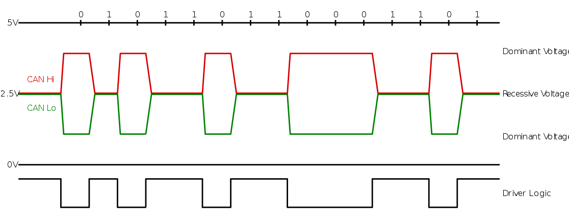
CAN Signalling, courtesy of Wikipedia
Why would I use CAN?
When transferring data between two microcontroller systems, people are probably already familiar with I2C and SPI, which are commonly used for low (I2C, 100-400kHz) or high (SPI, 100MHz+) speed data transfer between ICs. However, both of these protocols are really intended for operation over a short distance, ideally on the same board. Running I2C or SPI off-board, even for relatively short distances, can start to result in bit errors at higher speeds or in the presence of interference. The electrical integrity problems with I2C and SPI can be alleviated by using differential signals, as is the case with RS422/485. This allows RS485 to transmit data at high (multiple megabit) speeds over distances of 300-900 feet. This might satisfy our reliability or distance requirements, but none of these protocols bake in support for multi-master communication - SPI is very strongly based around a single-master design, and while I2C does allow for multiple devices to control the bus, there is no built-in arbitration support. Similarly for RS485, the application developer must roll their own packet structure and arbitration to handle bus contention.
CANBus performs quite well on some of these points, being:
- Differential for signal integrity
- Inherently multi-master
- Low component count (single transceiver IC + termination)
- Available in MCUs costing as little as a dollar
- Checksummed for data integrity
However, CANbus does have some drawbacks that make it a poor fit for other applications. These include:
- Very limited packet size of 8 bytes
- Maximum bus frequency much lower then SPI or RS485
- Maximum bus size of ~64 nodes
- Termination may need to be adjusted as nodes are added/removed
When deciding whether or not to use CAN, be sure to think carefully about the requirements of your application and whether or not CAN is the best fit.
Electrical specifications
For ‘High speed’ CAN (~512 Kbps), all controllers (nodes) in the system must be connected to a linear bus, with appropriate termination. This is to mitigate signal reflections, which can cause bit errors at receiving nodes. This does however mean that CAN buses can be slightly more work to add or remove nodes from, compared to systems that allow a ‘star’ topology (e.g. an ethernet switch). Instead each node must be connected directly to a previous node and to a subsequent node, or, in the case of the last node on either end, a terminating resistor of 120 ohms.
If one is willing to sacrifice some speed, ‘fault tolerant’ CAN (~128 Kbps) can be operated in a star topology, with the termination divided up and placed at each node. For more information, the Wikipedia page on CAN has some diagrams.
As an example implementation, I have created a small demo board in KiCad with switchable termination to be used for high-speed CAN communication. The design files are available here if you are interested in producing some yourself, or you can directly order them from PCBway here.
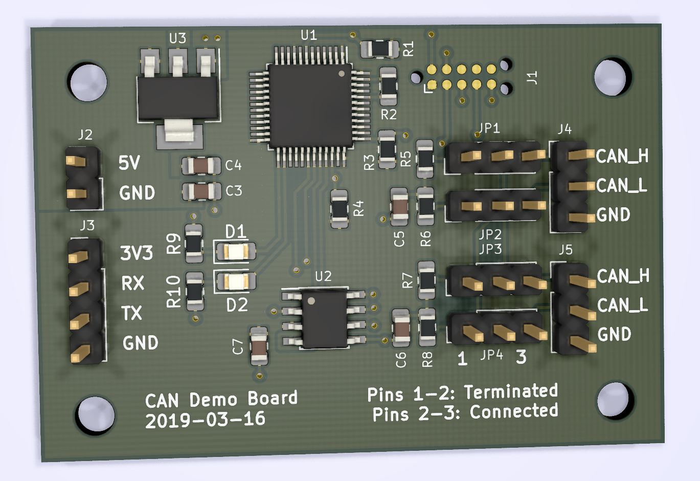
CAN Demo Board using STM32F091
Message format
CAN frames follow a defined format: all standard frames have an 11-bit identifier and up to 8 bytes of data. Extended frames allow 29 bit identifiers, but only the same 8 bytes of data. CAN frames also include checksums, and most CAN implementations in microcontrollers will automatically insert / verify checksums in hardware. The appearance on the wire of CAN frames is as follows:
CAN frame formats
- SOF: Start of frame bit (dominant). Used for synchronization.
- Identifier: The 11bit (standard) or 29 bit (extended) message ID
- RTR: Request to Transmit. Can be used by the application to indicate it wants another device to transmit.
- IDE: Whether or not this is an extended CAN frame. The IDE bit is 0 (dominant) for standard frames and 1 (recessive) for extended frames, thus making all standard frames higher priority than extended frames.
- DLC: Data length code. A 4 bit integer indicating the number of data bytes.
- Data. Data may be between 0 and 8 bytes for both standard and extended frames.
- CRC: 16-bit checksum for the frame data.
- ACK: When transmitting, the controller leaves the bus in a recessive state during the ACK bit. If any other device on the bus has received the just-transmitted frame and considers it valid, it will assert the bus during this bit, and the transmitter can know that the message was successfully transmitted.
- EOF / IFS: End of frame / interframe separator.
As may be clear from the 8 byte max payload size, CAN is not a good choice for applications that need to transfer large quantities of data. Instead it is much more suited for controls and small sensor data.
N.B: The ‘RTR’ bit in a CAN message is mutually exclusive with the data segment.
If you set the RTR bit, you may still specify a data length code (DLC) but the peripheral will not transmit any data bytes. Be careful when receiving frames that you ignore any data bytes ‘received’ in RTR frames, as they will simply be junk memory, which can led to pernicious bugs.
Using CAN with libopencm3
Now that we have an understanding of the CAN bus architecture, let’s actually build a small application that will send and receive data on the bus. Setting up the basics is relatively straightforward with a call to can_init():
// Enable clock to the CAN peripheral
rcc_periph_clock_enable(RCC_CAN1);

// Reset the can peripheral
can_reset(CAN1);

// Initialize the can peripheral
auto success = can_init(
    CAN1, // The can ID

    // Time Triggered Communication Mode?
    // http://www.datamicro.ru/download/iCC_07_CANNetwork_with_Time_Trig_Communication.  pdf
    false, // No TTCM

    // Automatic bus-off management?
    // When the bus error counter hits 255, the CAN will automatically
    // remove itself from the bus. if ABOM is disabled, it won't
    // reconnect unless told to. If ABOM is enabled, it will recover the
    // bus after the recovery sequence.
    true, // Yes ABOM

    // Automatic wakeup mode?
    // 0: The Sleep mode is left on software request by clearing the SLEEP
    // bit of the CAN_MCR register.
    // 1: The Sleep mode is left automatically by hardware on CAN
    // message detection.
    true, // Wake up on message rx

    // No automatic retransmit?
    // If true, will not automatically attempt to re-transmit messages on
    // error
    false, // Do auto-retry

    // Receive FIFO locked mode?
    // If the FIFO is in locked mode,
    //  once the FIFO is full NEW messages are discarded
    // If the FIFO is NOT in locked mode,
    //  once the FIFO is full OLD messages are discarded
    false, // Discard older messages over newer

    // Transmit FIFO priority?
    // This bit controls the transmission order when several mailboxes are
    // pending at the same time.
    // 0: Priority driven by the identifier of the message
    // 1: Priority driven by the request order (chronologically)
    false, // TX priority based on identifier

    //// Bit timing settings
    //// Assuming 48MHz base clock, 87.5% sample point, 500 kBit/s data rate
    //// http://www.bittiming.can-wiki.info/
    // Resync time quanta jump width
    CAN_BTR_SJW_1TQ, // 16,
    // Time segment 1 time quanta width
    CAN_BTR_TS1_11TQ, // 13,
    // Time segment 2 time quanta width
    CAN_BTR_TS2_4TQ, // 2,
    // Baudrate prescaler
    6,

    // Loopback mode
    // If set, CAN can transmit but not receive
    false,

    // Silent mode
    // If set, CAN can receive but not transmit
    false);

// Enable CAN interrupts for FIFO message pending (FMPIE)
can_enable_irq(CONTROLLER_CAN, CAN_IER_FMPIE0 | CAN_IER_FMPIE1);
nvic_enable_irq(NVIC_CEC_CAN_IRQ);

// Route the CAN signal to our selected GPIOs
const uint16_t pins = GPIO11 | GPIO12;
gpio_mode_setup(GPIOA, GPIO_MODE_AF, GPIO_PUPD_NONE, pins);
gpio_set_af(GPIOA, GPIO_AF4, pins);
In order to receive messages, in our CAN ISR we need to check to see which FIFO has pending data, and can then read off the message. For this demo, we’ll just put all of the messages in the same queue to be processed later.
void cec_can_isr(void) {
    // Message pending on FIFO 0?
    if (CAN_RF0R(CONTROLLER_CAN) & CAN_RF0R_FMP0_MASK) {
        receive(0);
    }

    // Message pending on FIFO 1?
    if (CAN_RF1R(CONTROLLER_CAN) & CAN_RF1R_FMP1_MASK) {
        receive(1);
    }
}

void receive(uint8_t fifo) {
    // Copy CAN message data into main ram
    Frame frame;
    can_receive(CAN1,
                fifo, // FIFO id
                true, // Automatically release FIFO after rx
                &frame.id, &frame.extended_id, &frame.rtr, &frame.filter_id,
                &frame.len, frame.data, &frame.ts);

    // Push the received frame onto a queue to be handled later
    msg_queue.push(frame);
}
Filters
So far, our application will receive and try to store all messages that appear on the bus. But for many applications, we may be able to ignore a lot of messages, and save ourselves some CPU time. To this end, the CAN peripheral on the STM32F091 has a series of filter banks that can be used to selectively accept different message types. The general structure of the filters is that you have an ID register used to input the data you want to match against, and then a mask register that defines which bits of ID register are to be matched. This can be a bit complex at first glance - let’s take a look at the relevant figure in the ST reference manual:
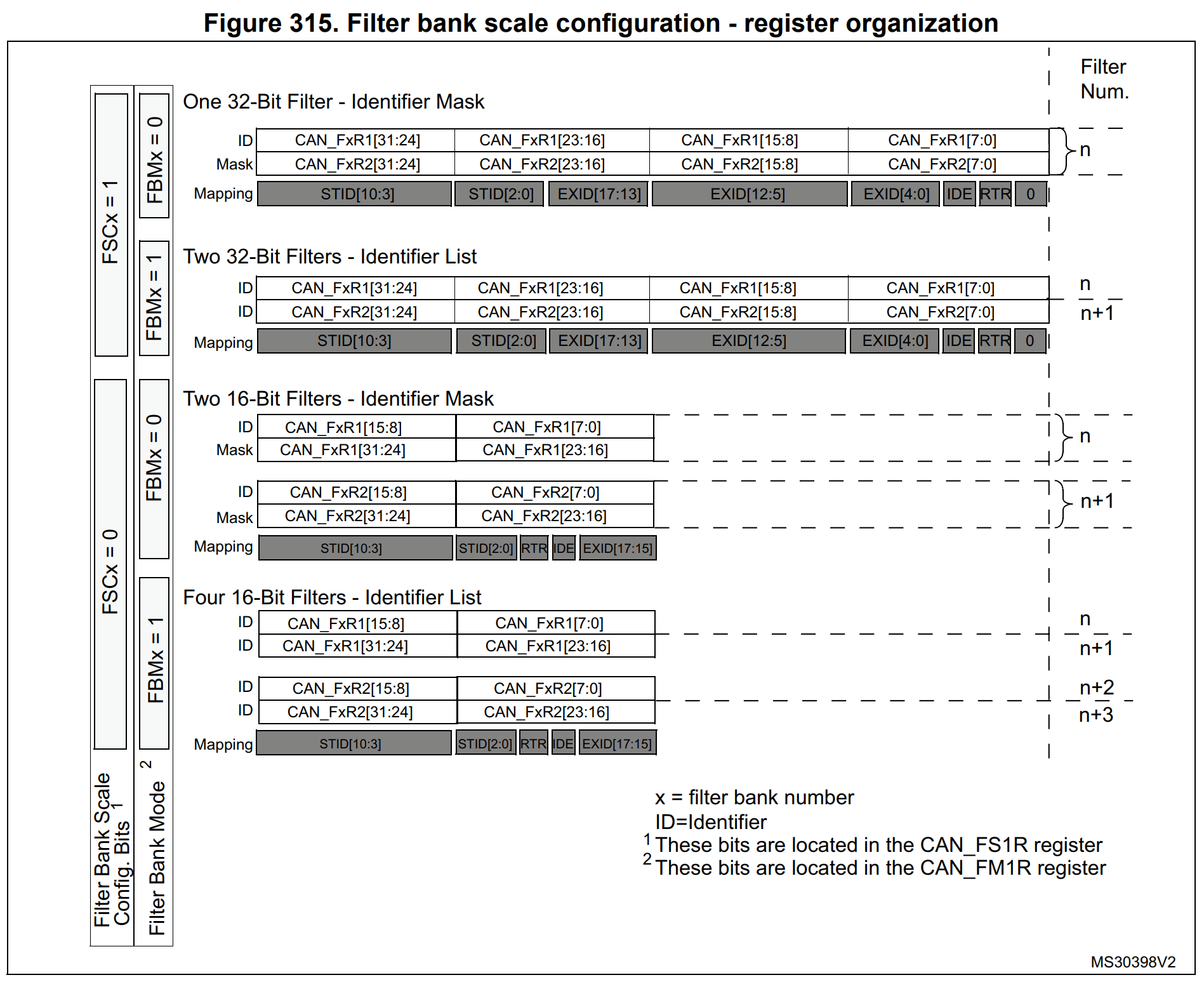
Filter Bank Configuration
As an example, let’s say that we have a device that only wants to receive two types of message:
- Messages with an ID less than 256, all of which are system broadcast messages
- Messages with an ID of 342 and the RTR bit set
Since these are both standard frames, we can use 16 bit filters, to save space. From figure 315 we can see that the first 11 bits of the register match against the ID, and bit 4 in the lower byte matches the RTR flag in the CAN message. So for our first filter, we want to assert that the message ID is <= 255. Since 255 is 0xFF, or 8 bits set, we know that any ID numbers above 255 will have one of bits 9-11 set. So to match only lower IDs, we can assert that the top three bits of the ID are zero. So for our first filter, we can create it like so:
const uint16_t id1 = 0;               // We want to assert the high bits are zero
const uint16_t mask1 = (0b111 << 12); // The only bits we want to compare are STDID[10:8]
For our second filter, we want to match the ID exactly, so we will load our ID register with our actual desired message value (342) and in our mask we will select all bits of the STDID field. Since we want to assert that the RTR field is also set, we will likewise place a 1 both the ID and MASK registers at bit 5, like so:
const uint16_t id1 = (
    (342 << 5) | // STDID
    (1 << 4)     // RTR
);
const uint16_t mask1 = (
    (0b11111111111 << 5) | // Match all 11 bits of STDID
    (1 << 4)               // Match the RTR bit
);
Once we have our filters, we can configure the CAN peripheral with them like so. All messages that match either of these filters will be placed into FIFO 0.
// Create a filter mask that passes all critical broadcast & command
// CAN messages
can_filter_id_mask_16bit_init(
    0,          // Filter number
    id1, mask1, // Our first filter
    id2, mask2  // Our second filter
    0,          // FIFO 0
    true);      // Enable
Putting it together
Now that we have our CAN peripheral initialized, let’s write a simple demo
application. We’ll use the demo board mentioned above (which you can order
directly from PCBWay
here)
to create a simple program that forwards bytes from the UART over the CAN
bus. In our main application loop, we’ll first take any characters that have
been received over the UART and transmit them over CAN. (Implementation details
of the Frame class can be seen
here
for those curious.)
  // Loop over any characters pending in the UART Rx buffer,
  // and send each one over the CAN bus as a single message.
  char c;
  while (Uart::get(&c)) {
    // Turn on our activity LED
    gpio_set(GPIOB, GPIO12);
    // Echo this character back to the serial console so we can see what
    // we've typed
    Uart::put(c);
    // Create a new CAN Frame holder
    CAN::Frame frame;
    frame.id = 1; // Our message ID
    frame.extended_id = false; // This is not an extended ID
    frame.rtr = false; // This is not a request to transmit
    frame.len = 1; // We intend to send one data byte
    frame.data[0] = c; // Our uart character is the first datum
    CAN::transmit(frame); // Send the frame to the CAN output mailbox
    gpio_clear(GPIOB, GPIO12); // Clear our activity LED
  }
We also need to receive frames off the bus and display the data. The receive interrupt we wrote earlier will queue the frames, so we can pop them off in order and print out the details.
  // Loop over any CAN frames pending in the CAN buffer, and print out
  // the ID of the message and all the data bytes.
  CAN::Frame frame;
  while (CAN::pop(frame)) {
    // Turn on our CAN activity LED
    gpio_set(GPIOB, GPIO13);
    // Print the frame ID and all data bytes as hex and plain characters
    printf("Rx ID: %u Data: ", frame.id);
    for (int i = 0; i < frame.len; i++) {
      printf("%02x:%c", frame.data[i], frame.data[i]);
    }
    printf("\n");
    // Turn off the activity LED
    gpio_clear(GPIOB, GPIO13);
  }
The full firmware listing can be found here.
In order to test this, we can assemble two test boards and flash the same
firmware to each. We can then connect the CANH and CANL pins of each board
using jumpers, and configure the termination using jumpers. Since each board is
connected to only one other board, we will set the jumper position for the
connected header to pins 2-3, which connects the jumper pins directly to the
transceiver. For the other set of jumpers, we select pins 1-2 to connect the
terminating resistors (in this case a split termination of two 59 Ohm resistors
and a 4.7nF capacitor) to the bus.
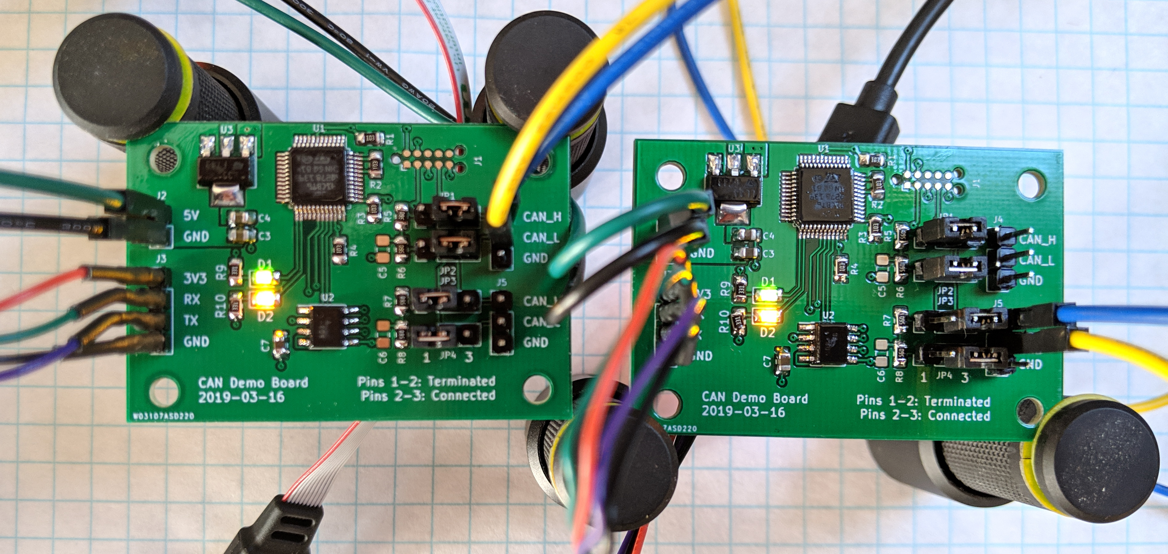
Two demo boards connected up
Once the boards are connected, we can connect a USB to UART adapter to each one and try sending some data back and forth. If everything is working properly, typing into the console of one board will cause it to send characters over CAN to the other, and vice versa.
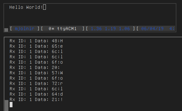
Communicating over CANBus
This concludes our overview of CANBus, and the implementation details of the CAN peripheral on the STM32 series of microcontrollers. Using the basics in this post you should be able to create far more interesting applications.
As per usual, the code for this post is available on Github.